Thursday, 23 March 2017

Motorised Laundry System (EMSA)

Motorised Laundry System (EMSA)
MUHAMMAD ISKANDAR BIN MOHD SANI                          01DIS15F1025
MUHAMMAD HAMIZAN BIN MD MARZUKI                        01DIS15F1006
AHMAD HANIF BIN BADRUL HISHAM                                  01DIS15F1007          
SYAFIQ AIMAN BIN SOBRI                                                        01DIS15F1079

INTRODUCTION
Motorised Laundry System

Nowadays, it is hard to keep track on the progress of our laundry that we kept on drying outside in the daylight. But, little did we know that the weather is not going to be sunny all the time because rains and heavy storm might come along in the way when we want to do our laundry.

Hence, we have created a Motorised Laundry System to prevent the laundry from getting ruined by the rain when we cannot collect it because of the weather is raining heavily or so. Besides, it eases our burden of having to carry the laundry there and then by just simplifying it with a single switch to do all the work for us.


The system works by pressing the switch to move the laundry outside and pressing it again to move the laundry back inside the area where there is a roof covering the laundry from rains.
This is a simple project from us using a PIC16F877A .This tools function when the user presses a button and dc motor serves to pull the clothes into the home area covered by the aid of the conveyor belt.This will make the user ease when the rain come and we just push the button to pull the clothes into the home area.
A simple prototype model


1     List of hardware, software and components

Hardware
i. DC motor
ii. LED GREEN
iii. L293D
iv.SWITCH
v.Capasitor
vi.PICKIT 2(PIC16F877A)

Software
i. MPLab ver 8.3
ii. Hi-Tech C compiler ver 2.3

     Circuit diagram

3    Coding
#include<htc.h>
void delay(unsigned long);
void forward(void); 
void stop(void);

__CONFIG (0x3F3A);
#define sw1 RB0 
#define MOTOR_2  RB4 
#define PWM      RC2

void main()
{
      TRISB=0b00000001;
      PORTB=0b00000000;
      TRISC=0b00000000;
      PORTC=0b00000000;

while(1)
{
     if(sw1==1) //press sw1, move clockwise
{

forward();
}
else
{
     stop(); //stop the motor
}
}
}
void forward(void)
{
MOTOR_2=0;
PWM=1;
}
void stop(void)
{
MOTOR_2=0;
PWM=0;
}

void delay(unsigned long)
{
 unsigned char i;
  for (i=0x08;i!=0;i--)
  {
   unsigned char j;
   for (j=0x00;j!=0;j--)
  {
  unsigned char k;
  for (k=0x00;k!=0;k--)
{
 }
 }
}
}
    

   Video


Wednesday, 22 March 2017

WATER LEVEL INDICATOR

DEC 5052 EMBEDDED SYSTEM APPLICATIONS

LECTURER : DR. HJ  HASNIM BIN HARUN

CLASS : EMSA

GROUP MEMBERS : ANIS SYUHADA BINTI AMRAN (01DIS15F1080)
                                   NOR IZATY BINTI ROSLAN (01DIS15F1039)
                                   NURUL HUSNA BINTI ABU BAKAR (01DIS15F1017)
                                   SITI SHUHADA BINTI JEFRIDIN (01DIS15F1028)

SYNOPSIS :
The Water Level Indicator employs a simple mechanism to detect and indicate the water level in an overhead tank or any other water container.
The sensing is done by using a set of three probes which are placed at three different levels on the tank walls (with probe 3 to probe 1 placed in increasing order of height, common probe (i.e. a supply carrying probe) is placed at the base of the tank). 
In this project we show the water level indicator using three transistors which conducts as level rises, a buzzer is also added which will automatically start as the water level becomes full, auto buzzer start with the help of microcontroller. With the help of this project we not only show the level of water on seven segment display but also indicate the water full condition using a buzzer.
a) list of hardware and software
hardware : 1. buzzer 
                  2. 7segment common cathode
                  3. transistor (BC547) 
                  4. resistor (270k, 100r, 470r) 
                  5. wire jumper
                  6. PIC16F877A
 software : 1. MPLAB IDE v8.83 
                   2. Proteus 8 Professional


b) Circuit diagram for this project 

  • when the container is empty, the output at 7segment is "E".


  • when water is medium, the output at 7segment is "C" and buzzer sound with delay 500ms.


  • when water is full, the output at 7segment is "F" and buzzer sound non stop.


c) Coding
#include<htc.h>

void delay(unsigned long);

int main(void)
{
//0-output 1-input
TRISB=0xff; //PORTB pins as input
PORTB=0xff;
TRISC=0x00; //PORTC as output
PORTC=0xff;
TRISD=0x00; //PORTD as output
PORTD=0xff;

unsigned char seg[10]={0x3f,0x06,0x5b,0x4f,0x66,0x6d,0x7d,0x07,0x7f,0x67};
while(1)
{
 if(PORTB == 0b00000011) //3rd probe, Tank full
{
RC1=1;
RC2=0;
RC3=0;

PORTD = 0b01110001;

RC0=1;;
}
 else if(PORTB == 0b00000101) //2nd probe, Half tank
{
RC1=0;
RC2=1;
RC3=0;

PORTD = 0b00111001;

RC0=1;
delay(500);
RC0=0;
delay(500);
}
 else if(PORTB == 0b00000110) //1st probe, Empty Tank
{
  RC0=0;

RC1=0;
RC2=0;
RC3=1;

PORTD = 0b01111001;
}
 else if (PORTB == 0b00000111)
{
RC0=0;

RC1=0;
RC2=0;
RC3=0;

PORTD = 0b00111111;
}
}
}

void delay(unsigned long x)
{
unsigned long i;
for(i=0;i<5000;i++)
for(;x>0;x--);
}
d) video


e) Conclusion
  1. Easy installation.
  2. Low maintenance.
  3. Compact elegant design.
  4. The Automatic water level controller ensures no overflows or dry running of pump there by saves electricity and water.
  5. Avoid seepage of roofs and walls due to overflowing tanks.
  6. Fully automatic, saves man power.
  7. Consume very little energy, ideal for continuous operation.
  8. Automatic water level controller provides you the flexibility to decide for yourself the water levels for operations of pump set.
  9. Shows clear indication of water levels in the overhead tank.


WELCOME HOME LCD DISPLAY TO GUEST WITH BUZZER

DEC5052 EMBEDDED SYSTEM APPLICATIONS

Group members:
  • Muhamad Syahir Faris bin Shahrudin (01DIS15F1015)
  • Mohamad Ismat bin Idrussaidi (01DIS15F1012)
  • Muhammad Faris bin Halim (01DIS15F1021)
  • Muhammad Qaiyum bin Arifin (01DIS15F1008)
Class: EMSA

Synopsis

This circuit will ring the house when guest or visitor press the button.


List of hardware/components:

1. LCD Display
2. Buzzer
3. PIC Microcontroller (PIC16F877A)
4. Microcontroller board
5. Switch
6. Wire

List of software:

1. MPLAB IDE v8.91
2. Proteus 8 Professional

Circuit diagram (using Proteus)


Coding


#include<htc.h>

//-------------- CONFIGURATION ----------------------------------------
__CONFIG (0x3F3A);
//-------------- DEFINE THE I/O PIN ------------------------------------
#define RS RA2 //RS pin of the LCD display
#define E RA3 //E pin of the LCD display
#define lcd_data PORTD
#define     d0 RD0
#define     d1 RD1
#define     d2 RD2
#define     d3 RD3
#define     d4 RD4
#define     d5 RD5
#define     d6 RD6
#define     d7 RD7
#define buzzer  RC1
#define SW1 RB0
//-------------- DEFINE VARIABLE DEFINITION --------------------------
//-------------- FUNCTION PROTOTYPE ----------------------------------
void delay(unsigned long a);
void e_pulse(void);
void lcd_clr(void);
void lcd_goto(unsigned char data);
void send_char(unsigned char data);
void send_config(unsigned char data);
void send_string(const char *s);
//-------------- MAIN FUNCTION (WRITE YOUR PROGRAM HERE) --------------
void main()
{                //set I/O input output
TRISA=0b00000000; //Configure PORTA I/O direction
TRISB=0b00000111; //Configure PORTB I/O direction
TRISC=0b00000000;
PORTC=0b00000000;
TRISD=0b00000000;
TRISE=0b00000000;
PORTA=0;
PORTB=0;
PORTC=0;
PORTD=0;
PORTE=0;
//Configure PORTD I/O direction
//setup ADC
ADCON1=0b00000110;
//set RA2, RA3 as digital and rest remain as analog I/O.
//Ensure pin share with analog is being configured to digital correctly
//Configure the LCD
send_config(0b00000001); //clear the LCD.
send_config(0b00000010); //Return cursor to home.
send_config(0b00000110); //Entry mode, cursor increase 1.
send_config(0b00001100); //Display on,cursor off and cursor blink off.
send_config(0b00111000); //Function set.
lcd_clr(); //Clear the LCD.
lcd_goto(0); //Put cursor on position 0.
send_string("PRESS BUTTON");
lcd_goto(20); //Put cursor on position 11.
send_string("TO RING");
b_light=1;
while(1)
{ 
if(SW1==0)
{ 
while(SW1==0);
lcd_clr(); 
lcd_goto(0);
send_string("WELCOME TO"); 
lcd_goto(20);
send_string("OUR HOUSE");
buzzer = 1;
delay(90000);
}
else
{  
lcd_clr(); 
lcd_goto(0);
send_string("PRESS BUTTON"); 
lcd_goto(22);
send_string("TO RING");
buzzer = 0;
delay(1);
}
}
}
//Delay function. The delay time depends on the given value.
void  delay(unsigned long a)
{ 
for(a=0xFF;a!=0;a--) ;
}
void e_pulse(void
{
E=1; 
delay(50); 
E=0; 
delay(50);
} //Send a pulse to the E pin of the LCD.
//Send the configuration to the LCD.
void  send_config(unsigned char data)
{ 
unsigned char test; 
unsigned char i;
RS=0;
for(i=0;i<8;i++) .
{ 
test=(data>>i)&0b00000001;
switch(i)
{ 
case 0:
if(test==1) 
d0=1; 
else d0=0;
case 1:
if(test==1) 
d1=1; 
else d1=0;
case 2:
if(test==1)
d2=1; 
else d2=0;
case 3:
if(test==1) 
d3=1; 
else d3=0;
case 4:
if(test==1) 
d4=1; 
else d4=0;
case 5:
if(test==1) 
d5=1; 
else d5=0;
case 6:
if(test==1) 
d6=1; 
else d6=0;
case 7:
if(test==1) 
d7=1;
else d7=0;
}
} 
delay(50); 
e_pulse(); 
}
//Clear the LCD
void lcd_clr(void)
{ 
send_config(0x01); 
delay(600);
}
//Set the location of the LCD cursor.
//If the given value is (0-15)  the cursor will be at the upper line.
//If the given value is (20-35)  the cursor will be at the lower line.
//Location of the lcd cursor (2x16):
// ----------------------------------------------------------
//  ||00|01|02|03|04|05|06|07|08|09|10|11|12|13|14|15|| 
// ||20|21|22|23|24|25|26|27|28|29|30|31|32|33|34|35||
void lcd_goto(unsigned char data)
{ 
if(data<16) 
{
send_config(0x80+data);
}
else 
{ 
data=data-20 ; 
send_config(0xC0+data);
} 
delay(200);
}
//Send a character to the LCD. 
void send_char(unsigned char data)
{ 
unsigned char test; 
unsigned char i;
RS=1;
//Set RS for data mode.
for(i=0;i<8;i++) //Loop for 8 times.
{ 
test=(data>>i)&0b00000001;
switch(i)
{
case 0:
if(test==1) 
d0=1; 
else 
d0=0;
case 1:
if(test==1) 
d1=1;
else 
d1=0;
case 2:
if(test==1) 
d2=1; 
else 
d2=0;
case 3:
if(test==1) 
d3=1; 
else 
d3=0;
case 4:
if(test==1) 
d4=1; 
else 
d4=0;
case 5:
if(test==1) 
d5=1; 
else 
d5=0;
case 6:
if(test==1) 
d6=1; 
else 
d6=0;
case 7:
if(test==1) 
d7=1;
else 
d7=0;
}
} 
delay(50); 
e_pulse();
}

//Send a string to the LCD.
void send_string(const char *s)
{ 
unsigned char i=0; 
while(s&&*s) 
send_char(*s++); 
delay(1000);
}

Video


Conclusion

This project can make the guest to know what to do when come to the house. This project also enable us to gain experience in electronic circuit and designing. However, a lot of difficulties were encountered in the process of realizing the project work like putting the components correctly in the board and detecting some errors.


Intrusion Alarm

DEC5052 - EMBEDDED SYSTEM APPLICATIONS

___________________________________

Lecturer name : Dr. Hj Hasnim Bin Harun

Member's name :

  • Mohamad Norizman Bin Azizan 01DIS15F1003
  • Arif Ibrahim Bin Arasmen           01DIS15F1040
  • Ezzul Hazziq BIn Zulkifli            01DIS15F1037
  • Muhammad Shauqi Bin Ismail     01DIS15F1035
Class : EMSA


Synopsis

This circuit will alert you from intruder who try to break into your house. It will automatically trigger the alarm when        This circuit is suitable place at door and even windows.


1- List of hardware,software and component

Hardware
i) Buzzer 9V
ii)Resistor 1K
iii)Transistor NPN 2N2222
iv)Switch
v)Microcontroller Board
vi)Wire
vii)Battery Connector

Software
i) MPLAB version 8.3
ii)Hi-Tech C compiler version 2.3
iii)Proteus professional

2- The circuit diagram for this project


3- Coding


4- Video


5- Conclusion


From the presentation day that we have done, it will improve our soft skills and also creativity in building the project. In addition, we can apply use this skill in our field of IT and future development.

SCREEN PROJECTOR

LECTURER NAME:
DR HAJI HASNIM B. HARUN

GROUP MEMBERS:-

NOR AFIQAH BT MOHAMAD RAZIF                                  01DIS15F1016
ARIFFA YUNALIS BT MOHD YAZID                                   01DIS15F1029
NURUL AFIFAH BT AZIZ                                                      01DIS15F1030
WAN HASIMAH BT MOHAMAD                                          01DIS15F1026

CLASS EMSA


PURPOSE


The aim is to allow the projector up and down using the switch when pressed. Thus we do not need  to do it manually and saves time.

A) List of hardware and software

Hardware
-Unistepper Motor
-Resistor 10k
-Resistor 1k
-Switch
-L293D

Software
-MPLAB IDE v8.83
-Proteus 8 Professional

B) Circuit diagram for this project


C) Coding

  #include<htc.h>
       void delay(unsigned repeat);
       void clockwise(void);
       void counterclockwise(void);
       void stop(void);

//--------------- CONFIGURATION ------------------------------------
       __CONFIG (0x3F3A);
//--------------- DEFINE THE I/O PIN -------------------------------
//--------------- DEFINE VARIABLE DEFINITION -----------------------

   #define sw1      RB0
   #define sw2      RB1
   #define PWM      RC2

//--------------- WRITE YOUR PROGRAM HERE --------------------------

void main()
{
       TRISB = 0b00001111;
       PORTB = 0b00000000;

       TRISC = 0b00000000;
       PORTC = 0b00000000;
while(1)
       {

       if (sw1==0&&sw2==1)
       {
       clockwise();
       }
       if (sw1==1&&sw2==0)
       {
       counterclockwise();
       }
       if (sw1==1&&sw2==1)
       {
       stop();
       }
        else
{}
}
}

void clockwise(void)
{
      PWM=1;
      PORTB=0x10;
      delay(1);
      PORTB=0x40;
      delay(1);
      PORTB=0x20;
      delay(1);
      PORTB=0x80;
      delay(1);
}


void counterclockwise(void)
{
     PWM=1;
     PORTB=0x80;
     delay(1);
     PORTB=0x20;
     delay(1);
     PORTB=0x40;
     delay(1);
     PORTB=0x10;
     delay(1);
}
void stop(void)
{
     PORTB=0xF0;
     sw2 = 1;
     PWM=0;
}
void delay(unsigned repeat)
{
unsigned char i;
for (i=0x10;i!=0;i--)
       {
       unsigned char j;
       for (j=0x20;j!=0;j--)
       {
       unsigned char k;
       for (k=0xC;k!=0;k--)
              {
              }
       }
       }
}

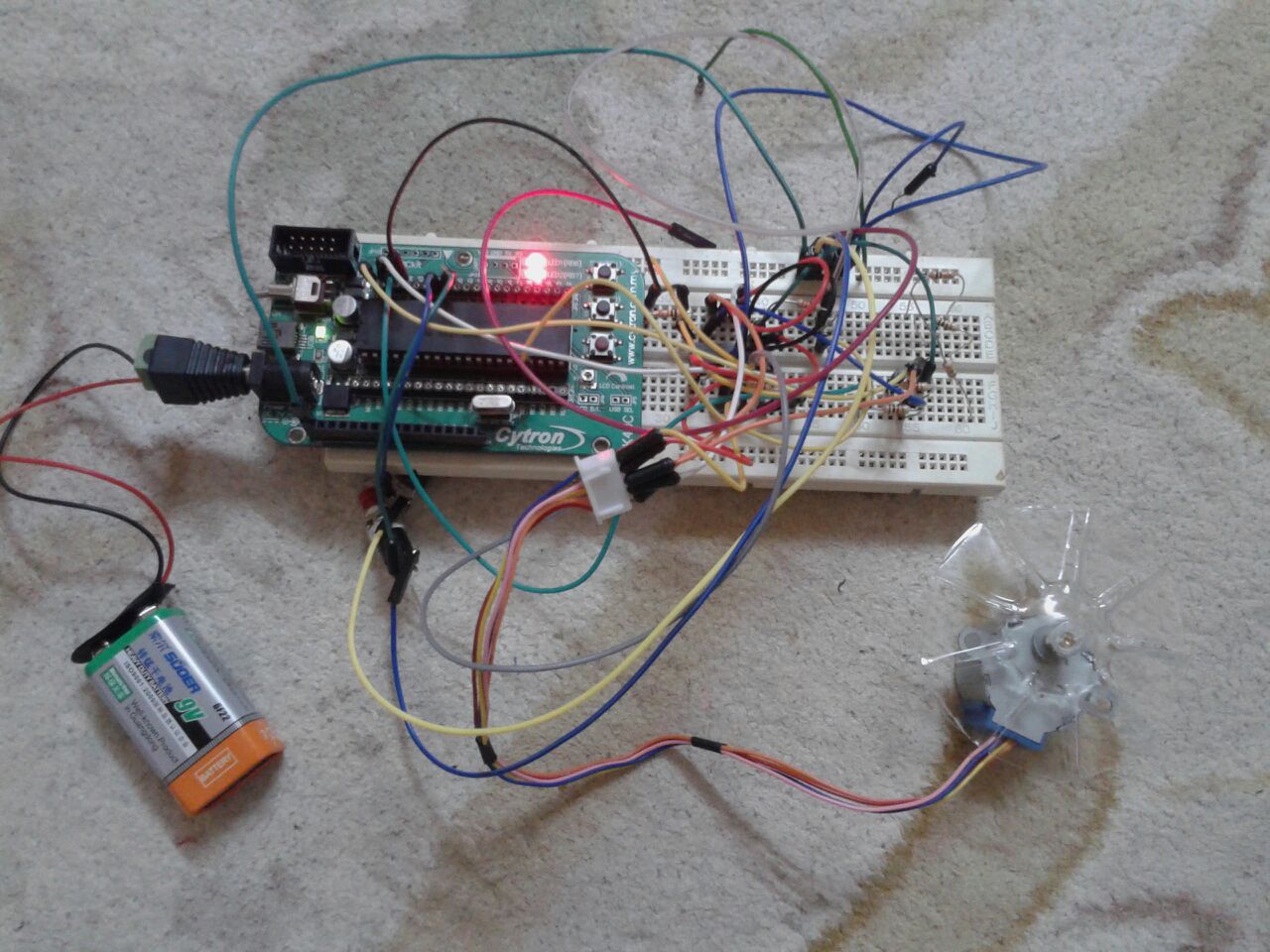
D) This picture show that circuit are connection


this picture show when we press the switch, the LED blinks.


E) Conclusion

The aim project is to move the Stepper Motor to clokwise and counter clokwise.